2003 Bmw X5 Radio Wiring Diagram
-
wiring diagram for connectors to monitor
Does anyone know what the wire assignments are for the two connectors that plug into the back of the onboard monitor? I have the widescreen 16:9 monitor and the back of the display head has two connectors that plug into like this:
They are both 12 pin connectors. I have a seen a couple of wiring diagrams that seem to indicate the assignments are this:
BMW
1-+12 VOLT IGNITION WIRE
7-Speaker LF+
2-+12 VOLT BATTERY WIRE 8-Speaker LF- 3-GND 9-Speaker RF+ 4-пустой 10-Speaker RF- 5-Speaker RR+ 11-Speaker LR+ 6-Speaker RR- 12-Speaker LR- But I'm not sure that is or either of these connectors. Anyone know what the wires are for on these connectors or a wiring diagram source?
"A good scientist is a person with original ideas. A good engineer is a person who makes a design that works with as few original ideas as possible. There are no prima donnas in engineering." - Freeman Dyson
-
Pin assignments at connector X18801 (Blue)
Pin assignments at connector X18802 (White)Pin Type Description / Signal type Connection /
Measuring notes1 E Nighttime illumination signal Light module 2 M Ground Ground point 3 A Left tape voltage control Radio 4 A Left tape ground control Radio 5 Not used 6 E/A I/K-bus signal link Connector, I/K-bus 7 E Terminal 30 Fuse F69 8 Not used 9 A Right tape ground control Radio 10 A Right tape voltage control Radio 11 Not used 12 E/A Background illumination signal On-board monitor Pin Type Description / Signal type Connection /
Measuring notes1 A Signal wire black Video module 2 M Shield black Video module 3 A Signal wire black Video module 4 M Shield black Video module 5 A Signal wire black Video module 6 M Shield black Video module 7 A Video module ground signal Video module 8 E Terminal 30 Fuse F69 9 Not used 10 Not used 11 Not used 12 E/A Background illumination signal On-board monitor
- - - Updated - - -On the white connector, 1, 3, 5 are R, G, B video in that order.
-
 Originally Posted by psjr
Pin assignments at connector X18801 (Blue)
Pin Type Description / Signal type Connection /
Measuring notes1 E Nighttime illumination signal Light module 2 M Ground Ground point 3 A Left tape voltage control Radio 4 A Left tape ground control Radio 5 Not used 6 E/A I/K-bus signal link Connector, I/K-bus 7 E Terminal 30 Fuse F69 8 Not used 9 A Right tape ground control Radio 10 A Right tape voltage control Radio 11 Not used 12 E/A Background illumination signal On-board monitor Pin assignments at connector X18802 (White)
Pin Type Description / Signal type Connection /
Measuring notes1 A Signal wire black Video module 2 M Shield black Video module 3 A Signal wire black Video module 4 M Shield black Video module 5 A Signal wire black Video module 6 M Shield black Video module 7 A Video module ground signal Video module 8 E Terminal 30 Fuse F69 9 Not used 10 Not used 11 Not used 12 E/A Background illumination signal On-board monitor - - - Updated - - -
On the white connector, 1, 3, 5 are R, G, B video in that order.
EXCELLENT! Thanks PSJR! where did you get this info? I was searching all over for this. (Maybe I used the wrong search terms on Google?)"A good scientist is a person with original ideas. A good engineer is a person who makes a design that works with as few original ideas as possible. There are no prima donnas in engineering." - Freeman Dyson
-
Anybody have the similar pinout/wire color chart for the sat-nav unit? (x1312 & x1313, violet and blue connectors on the back of the DVD unit). I'm returning a 12/99 car that was retrofitted with the TV tuner/switching module back to stock (well I'm keeping the upgraded MkIV navigation, but everything else has been removed). There's a homemade jumper harness in there, and lots of hacked wires, but I think I have enough connectors etc. to re-pin and splice things back to normal.
I have this, but no wire colors to go with it...
Last edited by Chamberlin; 01-01-2019 at 04:03 PM.
2006 R53 JCW (British Racing Green) - 1994 E31 840Ci 6spd (AVUS Blue)
2021 F56 JCW (Rebel Green) - 2000 E38 740i Sport (Titanium Silver)
2017 F26 X4 M40i (Carbon Black) - 2007 E91 328iT (Deep Green)
2012 E82 135i M Sport (Marrakesh Brown) - 2015 E84 X1 (Cashmere Silver)
2005 E53 X5 3.0i Sport (Kalahari Beige) - 2000 E36/7 M Roadster (Oxford Green)
2000 E38 740i Sport (Oxford Green) - 1999 E36 M3 Coupe (Fern Green)
1995 E31 840Ci Canadian (Oxford Green) - 2000 E36/8 M Coupe (Oxford Green)
2004 E46 330Ci (Oxford Green) - 2001 E36/8 Z3 3.0i Coupe (Oxford Green)
2002 E39 525i Sport (Oxford Green) - 2002 E36/7 M Roadster (Oxford Green)
2001 E53 X5 3.0i Sport (Oxford Green) - 2007 E63 M6 (Silver Grey)
1995 E31 840Ci (Oxford Green) - 2006 E86 M Coupe (Sepang Bronze)
2001 E39 530i Sport (Aspen Silver) - 2009 E92 M3 (Space Grey)
2001 E38 740i Sport (Sahara Beige) - 2008 E92 M3 (Melbourne Red)
2000 E38 740i Sport Canadian (Sahara Beige) - 1997 E31 850Ci (Jet Black)
-
Maybe this might help a bit:
https://store.bimmernav.com/blogs/in...ision-retrofitIn the picture for "Once the navigation drive has been removed, gently remove the whole trim piece." you can see the Trimble unit with the small coax/GPS/antenna cable with the one black connector (just to show what the MKII Trimble unit & attached wiring bundle looks like).
<== Steptronic Sealbeach740
2000 740i sport: 74k Green/Tan chrome MPars, clear corners, quad brake lights, AIC hi-beams, Hoen fogs, 16x9 screen, MKIV, TFT LCD screen in back, license plate backup camera with "on demand" switch, iPod audio/video (CDC/iPod audio switching, iPod video on 16x9 screen), Basslink, gauge rings, ///M pedals, switched steptronic +/- shifting mode, E46 paddle shifter steering wheel, Dinan engine & tranny software upgrade, DDEs controlled via Euro fog light switch, painted calipers with "BMW" lettering, windows up/sunroof close via remote.2003 540i sport: 81k, Sterling grey/grey, MKIV Nav, PDC & CWP - Added license plate backup camera with "on demand" switch, paddle shift steering wheel, windows up/sunroof close via remote, Akebono's, painted calipers with "BMW" lettering, quad brake lights, iPod audio via AUX mode/video via 16x9 screen, BMW TV tuner, ///M pedals & gauge rings.
- Thanks SealBeach, your car's specs are just like mine! Originally Posted by sealbeach740
Maybe this might help a bit:
https://store.bimmernav.com/blogs/in...ision-retrofitIn the picture for "Once the navigation drive has been removed, gently remove the whole trim piece." you can see the Trimble unit with the small coax/GPS/antenna cable with the one black connector (just to show what the MKII Trimble unit & attached wiring bundle looks like).

Appreciate the link, there's a lot of good stuff on Bimmernav, but unfortunately nothing I can use to piece back together the factory harness to the MkIV unit. I made some good progress today though, getting the speaker wires to the C43 reconnected, the reverse light taps put back together, and some other obvious wires re-spliced using unused wires that were just floating inside in the home-made E39 harness you used. I think you must have used an aftermarket 12 pin black (AMP style) connector to attach to the original wires, and moved the original blue connector over to the custom harness. So I'm at a point where it's just a matter of figuring out which color wires from the factory harness go to which pins on the blue and violet connectors. I know there are some balanced line level wires in there too, in addition to the colored 18ga wires.
P.s. The SMB coax jumper for the CD changer arrived yesterday, thanks!
Last edited by Chamberlin; 01-01-2019 at 08:04 PM.
-
While I don't recall the details, the TV tuner came with a custom cable. That cable was used to add the TV tuner into the mix with the Nav.
I know, not much detail, that was over 10 years ago.....Of course, it started out as a simple mod to add the tuner, then blossomed/grew out of control from there!- thanks for letting me know you got that coax cable.
Last edited by sealbeach740; 01-01-2019 at 11:24 PM.
2000 740i sport: 74k Green/Tan chrome MPars, clear corners, quad brake lights, AIC hi-beams, Hoen fogs, 16x9 screen, MKIV, TFT LCD screen in back, license plate backup camera with "on demand" switch, iPod audio/video (CDC/iPod audio switching, iPod video on 16x9 screen), Basslink, gauge rings, ///M pedals, switched steptronic +/- shifting mode, E46 paddle shifter steering wheel, Dinan engine & tranny software upgrade, DDEs controlled via Euro fog light switch, painted calipers with "BMW" lettering, windows up/sunroof close via remote.2003 540i sport: 81k, Sterling grey/grey, MKIV Nav, PDC & CWP - Added license plate backup camera with "on demand" switch, paddle shift steering wheel, windows up/sunroof close via remote, Akebono's, painted calipers with "BMW" lettering, quad brake lights, iPod audio via AUX mode/video via 16x9 screen, BMW TV tuner, ///M pedals & gauge rings.
- Yes indeed, I believe this is the factory jumper cable from the site you linked: Originally Posted by sealbeach740
While I don't recall the details, the TV tuner came with a custom cable. That cable was used to add the TV tuner into the mix with the Nav.
tvkit1.jpg
Here's the custom E39 jumper harness that came out of your car:
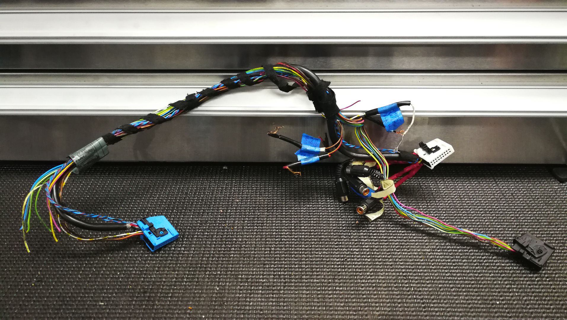
There's this one too, but it's obviously an aftermarket piece from somebody like bimmernav (goes to coder?):
So this is where I'm at now:

Aside from protecting the cuts on the speaker lines (from the now removed wire taps), everything on the right side half is accounted for and should be good to go (amplifier connections, CD changer wires, and three black antenna coax lines coming from the C pillars and parcel shelf area).
On the left half of the picture, I need to build a factory blue connector which will replace the aftermarket black connector (which contains some black factory(?) balanced line level signal cables), and also verify and complete the factory violet and factory black connector's wiring. I've already spliced back in the yellow/red and yellow/white sections on the violet connector that were chopped out (using the proper wires from the un-used spares that I found in the custom E39 harness loom). There are also three loose unused wires with their original pins still attached (brown [usually ground], red with yellow stripe and white with yellow bands), so I need to determine which connectors and pin locations they go to. Lastly, there is a hanging purple and hanging black wires which are coming from the aftermarket black connector I need to figure out as well.
Closer up view:
The TV Tuner (which really should be called an audio/video switching unit with integrated off-air tuner!)
OK, so here's a question for you all... Being a BMW collector, I happen to have an unmolested 2002 525i Sport with factory MkIV navigation sitting in my driveway. What are the chances I could use its blue and violet connector wiring assignments as a guide for this 740i restoration?
Last edited by Chamberlin; 01-05-2019 at 05:45 PM.
-
Just wanted to update, that I got everything working on the 1st attempt! GPS locked into my location even inside the garage! CD changer audio works! (I'm guessing the coax SMB connector is digital audio, plus digital control signals, hence no 6 pin connector is present nor needed - that had me baffled for a bit). I did end up using my E39 525i MkIV nav computer wiring to help confirm some stuff, but the violet connector only had two wires, whereas the E38 had many more. I re-pinned what I could to match the E39, and everything worked! I was left with the black connector un-connected to anything; and it's two de-pinned wires still hanging loose, so I just taped them up and stuffed them along with the black connector behind the CD changer. If I ever find out what that connector is for, I will re-pin the two removed wires, and tuck it away further. I'm guessing it's for another module or something, and Sealbeach740 was just using it to get access to some more fused power, control, and ground lines.
I'm thinking I might search for a proper TV tuner adapter cable and try to re-install the tuner as the factory would. Not sure if BimmerNAV sells the cables separately.
Thanks for everyone's help!
Last edited by Chamberlin; 01-07-2019 at 12:10 AM.
-
Hi there,
I was searching for some stuff how to retrofit a navigation system into e39 540i which originally came with a business radio unit. I went to a scrap yard and came across an e39 530i 2002 with MK III navigation system. Anyway it looked like someone before me was trying to pull it out of the car but gave up for some reason. I took the challenge and I've managed to pull the wire loom from the car with LCD display, radio unit BM 53, amplifier Alpine. The only thing I'm missing is a GPS module. Unfortunately someone cut the plugs off the LCD unit and now I'm struggling to connect the cut ends of wires together. I saw the diagrams for the connectors in this post but it doesn't help me with my issue. I was hoping someone can help me.
Also I didn't know much about retrofitting a MKIII system before removing it from a wrecked car so now I'm wondering how big of a job it is to connect it to the existing wiring in my e39. Any help would be greatly appreciated.Thank you
IMG_2459.jpg
IMG_2458.jpg


Source: https://www.bimmerforums.com/forum/showthread.php?2345163-wiring-diagram-for-connectors-to-monitor
Posted by: natividadbonnine0193087.blogspot.com

Post a Comment for "2003 Bmw X5 Radio Wiring Diagram"